Porcelain, Tungsten, and other yaks
Yak shaving: Any apparently useless activity which, by allowing you to overcome intermediate difficulties, allows you to solve a larger problem.
—Wiktionary
I didn’t realize just how lucky I was when I repaired Milly’s previous electron emitter. I was able to replace the tungsten tip while leaving the rest of the tungsten wire assembly in place.
No such luck this time. When I pulled the old tip off with tweezers, the supporting wire broke in half. No problem, I thought. How hard could it be to spot weld an 8mm semicircle of tungsten wire to a couple of posts?
After four attempts and a few weeks later, I decided to take a step back and reassess the situation.
Meet the emitter
Milly’s electron emitter is a large module consisting of a stainless steel mount with a razor edge, a hefty chunk of porcelain, some highly polished steel, and a gold foil aperture.
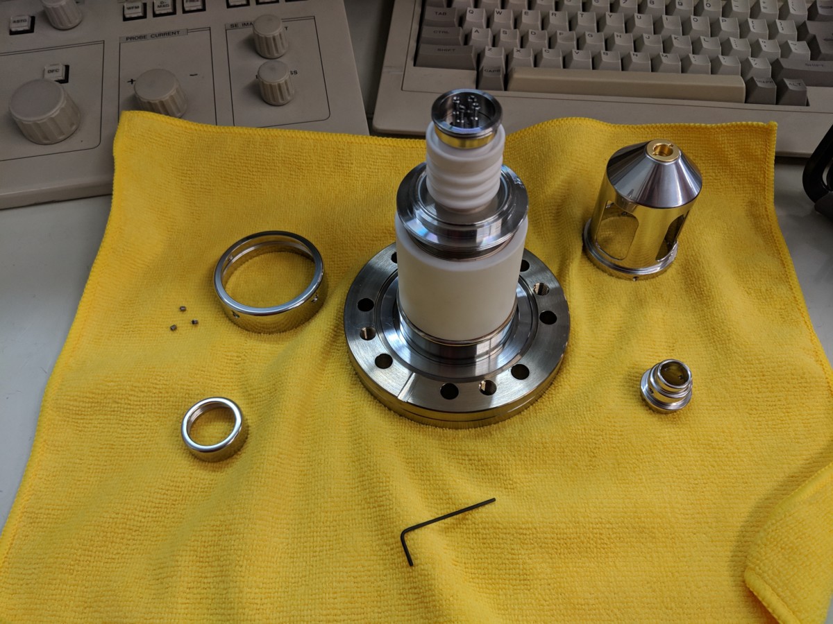
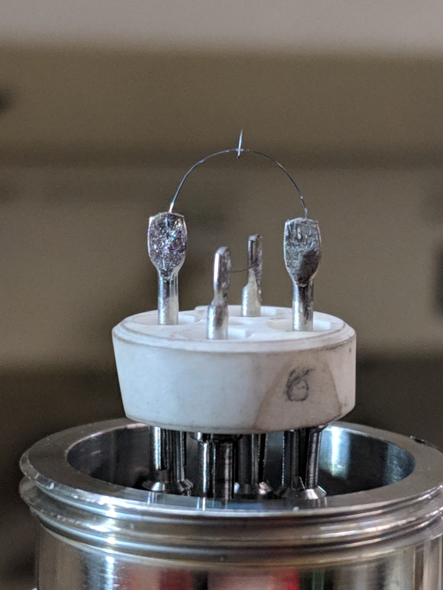
There’s nothing wrong with any of those bits. The trouble is the emitter itself: a 14mm x 5mm porcelain base with four steel pins in it. Two pieces of tungsten wire are spot welded to the pins, forming the extraction voltage electrode and the electron emitter itself. That little pin on top is just over 2mm tall, and only a couple of tungsten atoms wide at the tip.
The emitter is not intended to be user-serviceable. The entire module is usually sent back to the manufacturer (under service contract) and replaced with a new one. I imagine few people outside of JEOL have actually seen the emitter base, let alone tried to repair one.
Fixing that wire loop involves removing the broken wire, performing three spot welds, annealing the wire, and perfectly aligning the tip and the extraction electrode under the gold aperture.
The wire is 100 microns in diameter, roughly as thick as a coarse yak hair (or about twice as thick as the hair on your head). Welding tends to embrittle the wire as it rapidly forms tungsten oxides, so a shield gas (such as argon or nitrogen) is needed. I work under a microscope with improvised tools just so I can see what I’m doing.
Once I have a candidate emitter, how do I know if it worked?
Less than rapid iteration
The FEG cold cathode emitter can only work its magic in an ultra-high vacuum, about 10-7 pascal (~10-9 torr). That means that each time I want to test it, I need to reassemble the module, install a disposable copper seal, screw down 8 bolts… and wait 36 hours. An overnight bake-out is necessary to achieve UHV. Only once the scope gets hot enough to eject water from the insides of the chamber, then cool enough to operate again, can I see if an electron beam can be produced.
So far: four tries, three complete failures, and one almost success (it made a beam!) that turned into crushing defeat (it broke while performing conditioning before I could take a single image).
Weeks of work. Disaster.
Which brings us to yaks.
I only have one emitter. Every time the emitter module is out of the scope, the column is at atmospheric pressure, getting wet and doing slow damage to the ion pumps. It sits that way for a couple of hours while I remove the old emitter and make a new one.
If I only had an extra base or two, I could reduce my time-to-fail. I could iterate more quickly and make a perfect emitter (and a backup!) at my leisure. Once I’m confident that it’s perfect, I could then quickly swap it out and bake out the system.
But I have yet to find one of these bases for sale from the usual supply houses. I’ve only seen two for sale on eBay, and they were both (unsurprisingly) attached to microscopes.
Clearly I need to make one.
Modeling clay
One quick trip through Fusion 360 and I had a reasonable model. (Okay, it was more like an evening followed by an afternoon or two of tweaks, but I’m still happy with the result.)
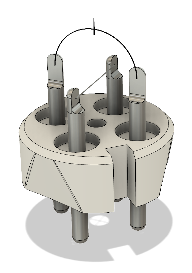
Having an accurate model means that I can print out prototypes, fixtures, or molds, and even scale up to accurately account for the expected shrinkage when baking out the porcelain.
It’s really too bad that you can’t use plastics in ultra-high vacuum (due to off-gassing). Making porcelain is going to take a few more steps than it took to print these prototypes.
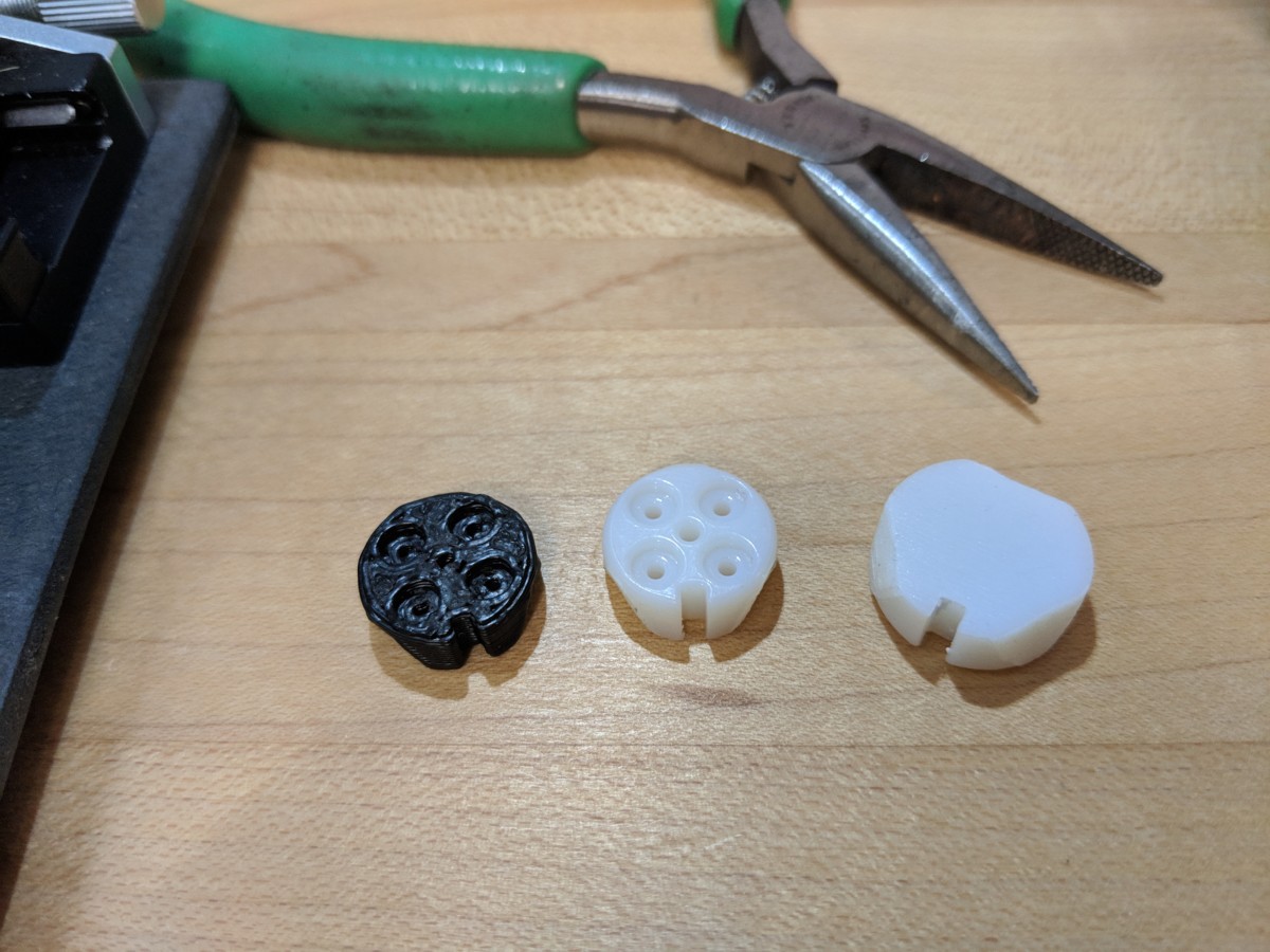
I previously used porcelain slip to make the high voltage switch inside the Tesla gun. At the time I used a 3d powder printer to make a mold. This time I printed the positive form in resin at 115% scale (and some at 120% scale) and made a simple plaster mold.
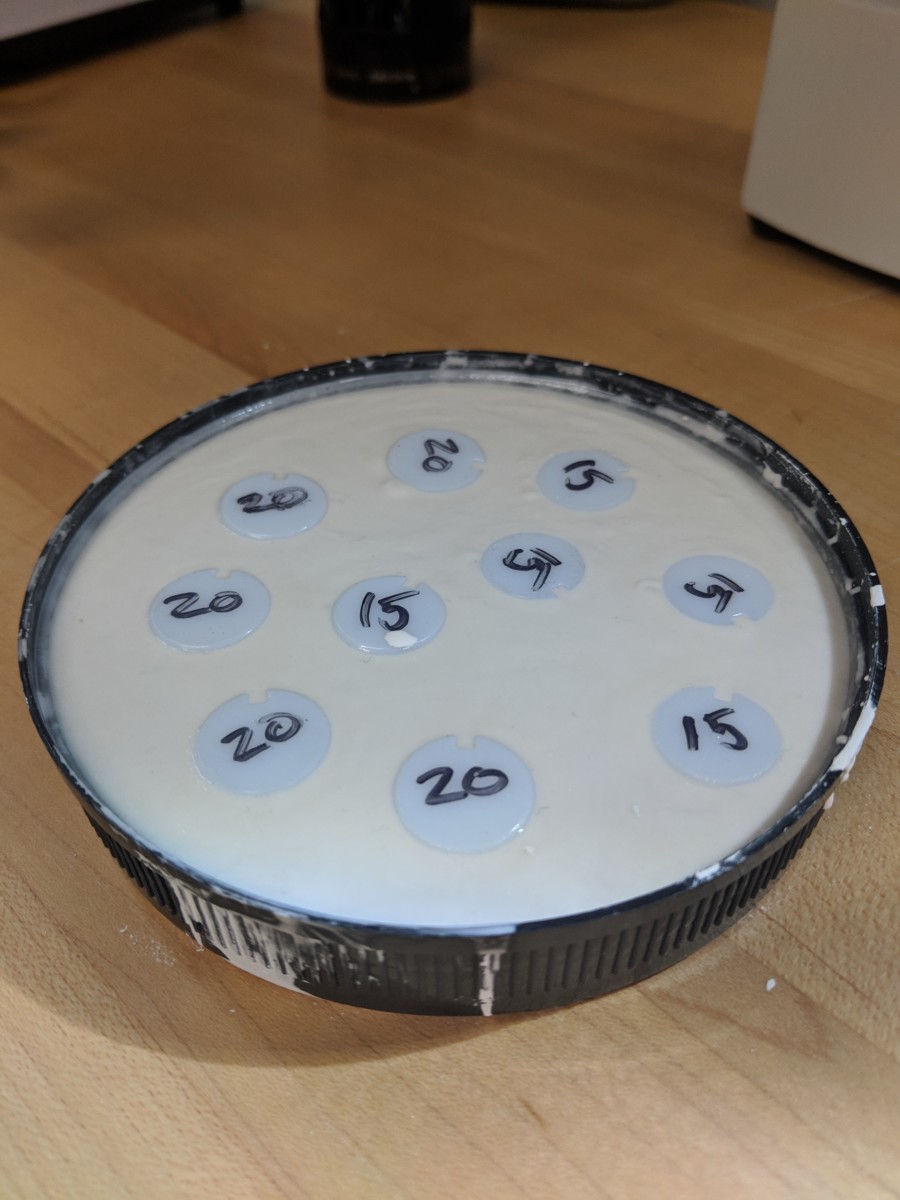
Now that I’ve got a mold, I can pour in some slip, let them dry, and drill the holes by hand.
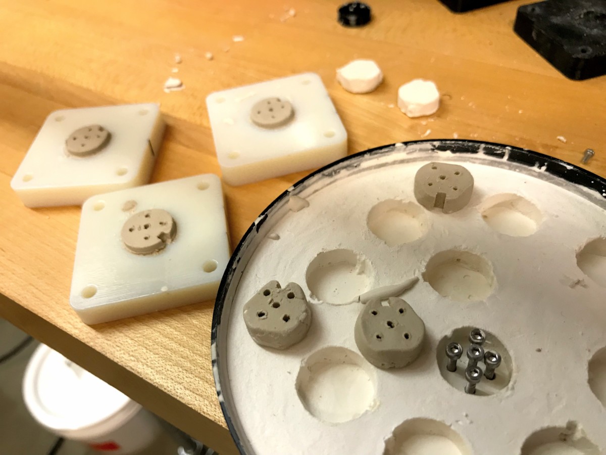
A couple more resin printed molds help with the job of cleaning up the surfaces and drilling holes in the proper place. A four and a half hour bake in the kiln later, and these two early attempts look promising. But I still see plenty of room for improvement.
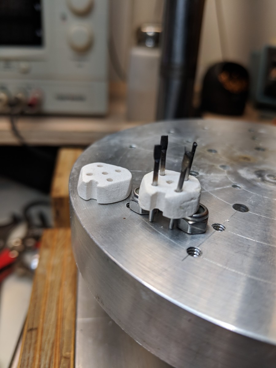
They’re clearly not ready for service yet, but I’m happy with the progress so far.
Tune in next time when I bake off another batch and tackle the spot welding problem.